Awesome info, thanks. So with 50/50, it looks like 200 PSI is the limit until you get over 100 degrees F at which point it goes down (for 1" and smaller).
Being able to touch the compressor head while it’s running is very impressive, as are the write up & pics. Well done!
Here is my modified, custom XD3000 compressor, w/ the custom air shroud, the integrated blower fuse holder, the pigtail for the remote switch w/ remote low-battery indicator and the blower.
Using my circuit, I was able to retain the local power switch, in addition to the new one on my dash panel.

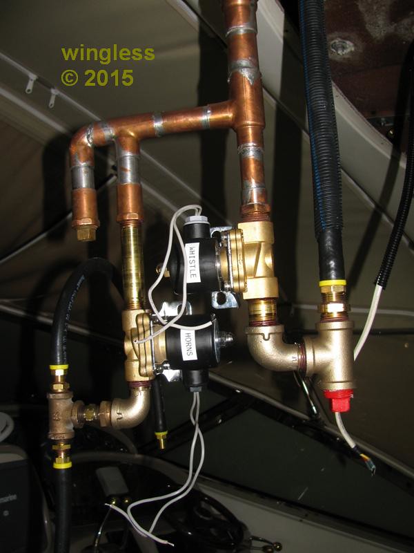
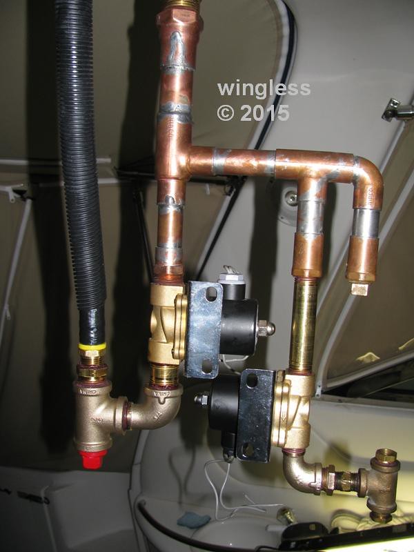
This is the air valve manifold, buried in the arch below my open array radar pedestal. The manifold is secured in-place by four tapping screws into the radar arch reinforcement holding the valve brackets.
There is one 3/4" HornBlasters valve for the whistle and a ½" HornBlasters valve for the horns.
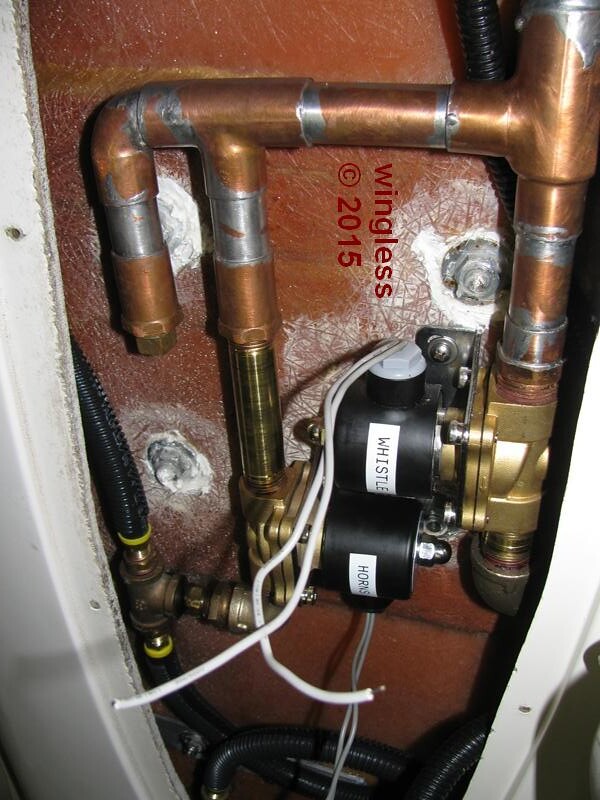
Keep an eye on the top of those solenoids. I found that mine were subject to plenty of corrosion, even though it’s mostly superficial.
Thanks for the tip.
My hope is that this dry and protected volume won’t lead to corrosion, even in the marine environment.
Here is the solenoid valve wiring.
The two wire splice was implemented to ensure that the splice won’t fail. It also was implemented to fully comply w/ the marine ABYC safety specifications.
The cable feeding each solenoid from the dash switch is a two conductor 16 AWG marine duplex cable w/ individually tinned conductors. These are continuous home-run feeds to the ground buss bar and the dash panel switch. ALL of the wiring on my boat is encased in split loom and secured along the length, both w Adel clamps and w nylon wire ties w screw anchor loops. The wire ends are also labeled, all to fully comply w ABYC.
The splice is done w a 16-14 to 22-18 Step Down Butt Splice using my Xcelite ECP-100 Ergo-Crimp Tool.
The splices are staggered, covered w adhesive-lined heat shrink tubing and strain relieved.


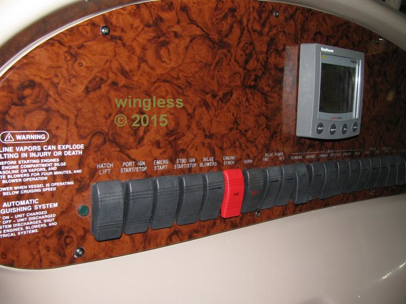
Here are images of the dash panel and wiring.
The wiring on the boat is encased in split loom throughout the boat. The dash panel enclosure is the only place where the wiring and cabling are run w/o split loom.
There were unused switch locations w/ blank filler panels that have been used for this project. My boat does not have the engine synchronizer and does not have a bow thruster. Those switch locations were used for the air horn / whistle and for the compressor, respectively.
The new red switch is a double-pole double-throw switch for either the air horns or the whistle.
The dirty / yellowish coating on the original wiring parts is a spray-on coating the factory applied to fixed-location parts, like buss bars and connectors.


More buttons than mission control. I like the Autopilot one… always reminds me of this 

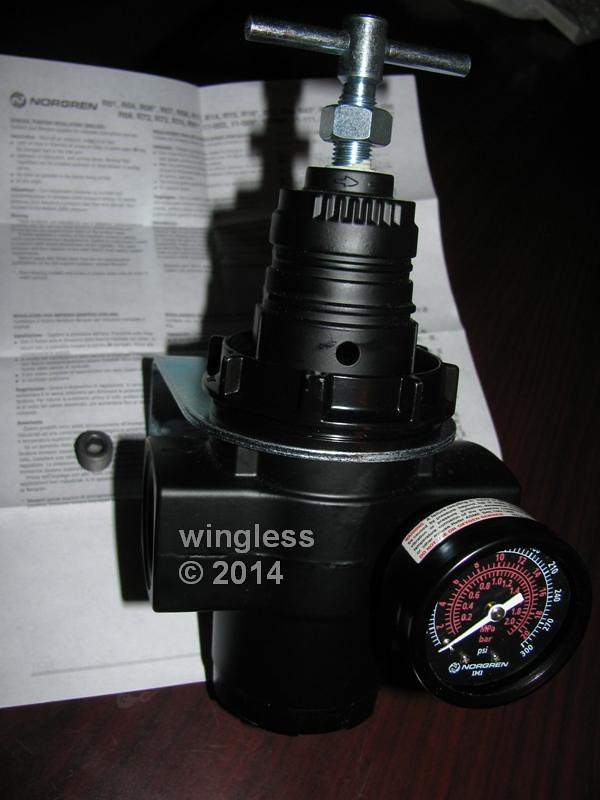
My Norgren 17 Series General Purpose Regulator, p/n R17-801-RGSA, just started leaking lots of air.
The air is exiting the regulator at the relieving port, the ¼" hole above the large bracket nut in the first image, where the downstream excess pressure is dumped when using the handle to drop the pressure.
It leaks even when the output pressure is dialed down to zero.
If I plug the relieving port w/ my thumb, then the output pressure climbs to the inlet pressure.
It is acting like the diaphragm that stops / regulates output pressure has crud on the seat, preventing the seal from input pressure to output pressure.
The data sheet says: “Can be serviced without removal from the air line”.
Has anyone performed service on this regulator?
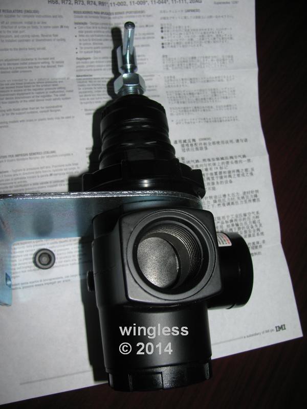
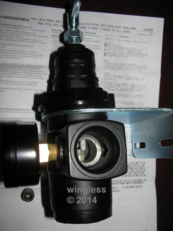
Mine has 1" NPT input / output ports. This is a high CFM relieving regulator w/ large ports and w/ two full-flow ¼" gauge ports, one having a 0 to 300 p.s.i. gauge. The regulator has a working output pressure adjustment range of 10 to 250 p.s.i. The optional mounting bracket is used to mount the regulator.
Norgren R17 Regulator - Gauge Side
Norgren R17 Regulator - 1" NPT Input Port
Norgren R17 Regulator - 1" NPT Output Port
I have the smaller version of that, but I haven’t ever opened it. As far as I know, the plastic bottom screws off to access the internals.
That is correct, thank you.
The Norgren technical support representative provided this R17 Installation & Maintenance Instructions and instructed me to remove the bottom plug, clean the internals and reassemble.
This will be tried shortly.
The regulator relief port leak was corrected by disassembling the lower cap, cleaning the parts, lubricating the parts and reassembling the lower cap.
This threaded aluminum lower cap is hand-tight.
There was crud on the seat and some water in the cap.
Everything was cleaned and lubricated.
The hand-tightened cap was replaced.
The relief port is not leaking air anymore.
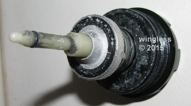
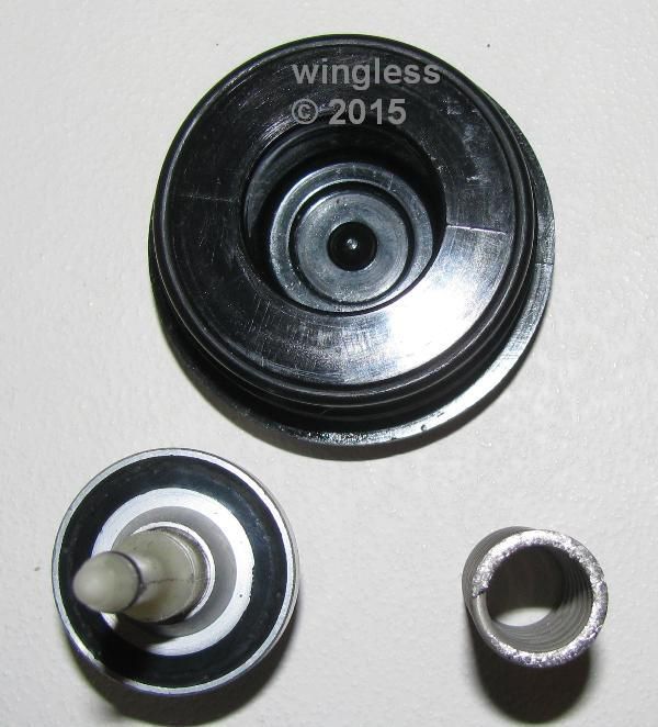
Dirty Valve Seal, Spring and Cap
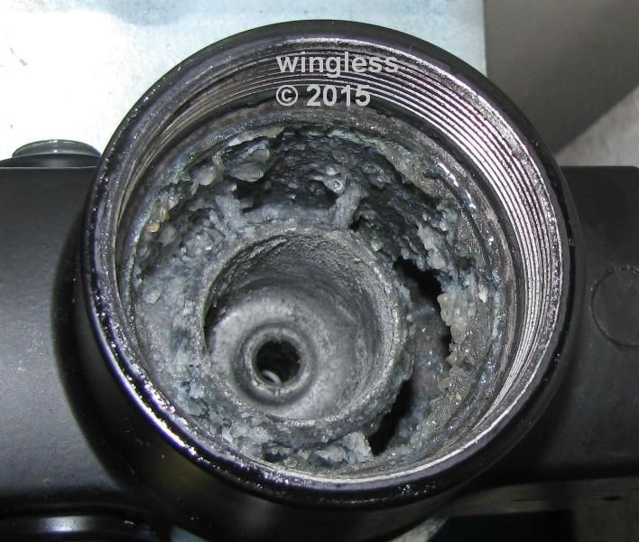
Dirty Regulator Body
Clean Valve Seal, Spring and Cap
The regulator relief port leak was corrected by disassembling the lower cap, cleaning the parts, lubricating the parts and reassembling the lower cap.
This threaded plastic lower cap is hand-tight.
There was crud on the seat and some water in the cap.
Everything was cleaned and lubricated.
The hand-tightened cap was replaced.
The relief port is not leaking air anymore.
Dirty Valve Seal, Spring and Cap

Dirty Regulator Body

Clean Valve Seal, Spring and Cap

Do you run your vessel on salt water? I’d hate to think that that was salt and that it accumulated that quickly. Perhaps it is manufacturing grease that has gone bad?
If it is salt, I don’t even want to know what it might be doing to the inside of your compressor.
The boat is used only in salt water. The air going into the compressor is clean and is fine.
The “white crud” is a manufacturing grease applied to the interior of the regulator.
The manufacturing grease looks bad, but appears to be okay.
It looks like speck of crud got stuck on the seat, preventing the valve seat from sealing. That spec is circled in this image.

Here is an image showing the freshly cleaned and lubricated Norgren R17 valve body.
The brown stuff is the Dow Corning Molykote 44 Grease I used to lube these parts. This is compatible w/ rubber and plastic parts. The service temperature is specified for -40°F to 400°F.
Looking up into the high-flow Norgren R17 Regulator body, the large input port is on the left and the large output port exits the center bore on the right (partially obstructed by the glob of grease).
In retrospect, my new system has always been dribbling some air, requiring periodic cycling of the compressor to top off the tank. In the day since I cleaned the seat it looks to be holding air well. My guess is that the assembly solder flux pushed through the plumbing and got trapped by the grease and on the seat / seal.

Here is an image w/ the grease globs moved.

The topic was reworked to replace the images w/ Flickr. This was as much fun as it appears.
That aluminum regulator was a bad idea in the salt water marine environment.
It had been retired long ago, with all my usage at tank pressure, set to kick off at about 130 psi.
This system has been a solid performer over the years.