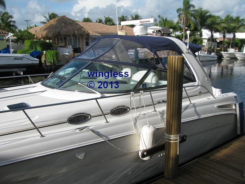
My 2000 380 Searay Sundancer is about to get a custom air compressor now, then add a horn and maybe an air whistle system later.
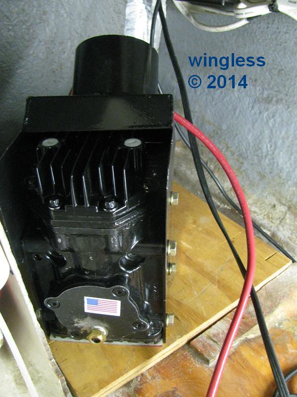
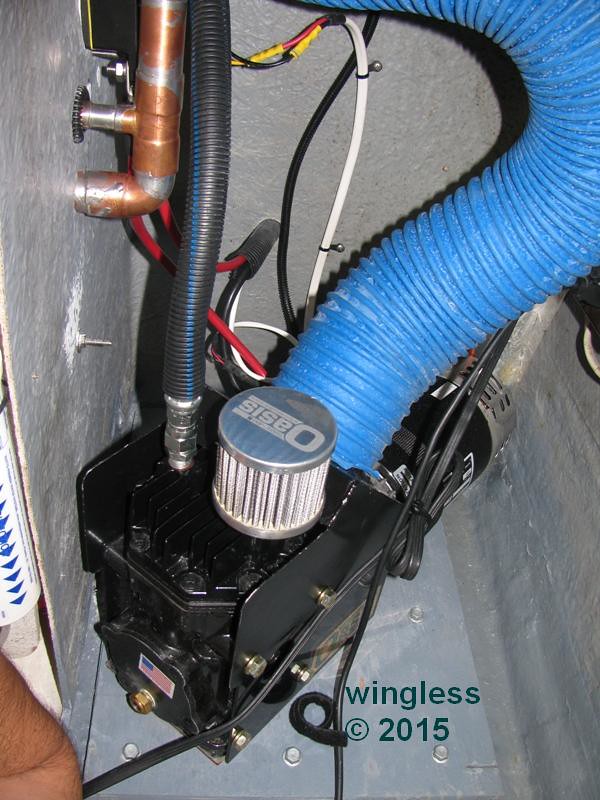
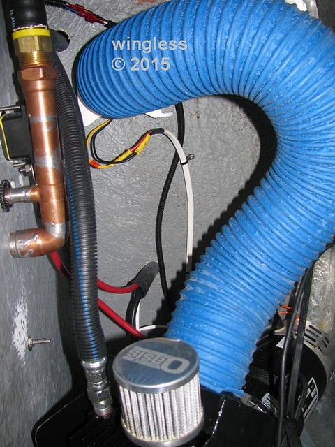
The first step was selection of a compressor. I have a Oasis XD3000-12 compressor. This has been customized to add features like forced air cylinder / head cooling, like is present on the XD4000-12 compressor, only mine has much more airflow and mine has ductwork to suck in fresh, exterior air.
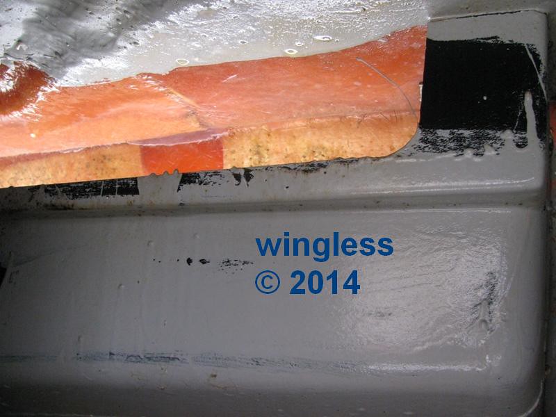
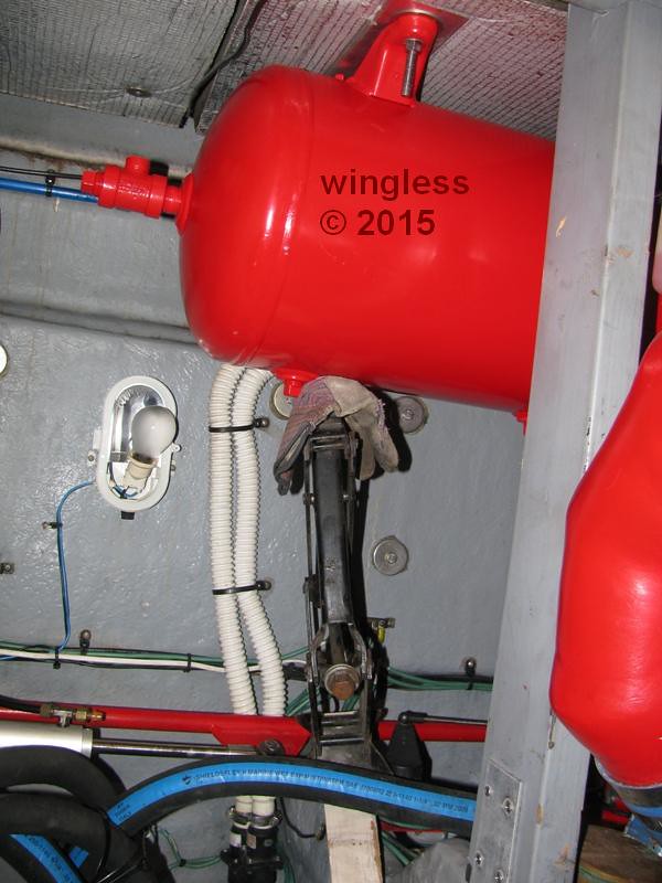
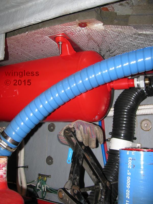
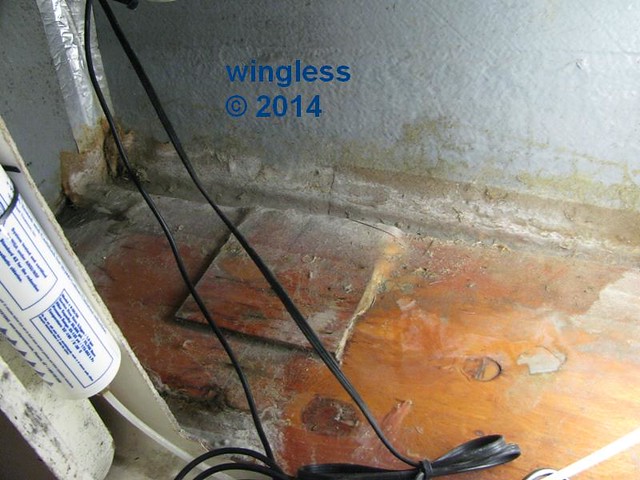
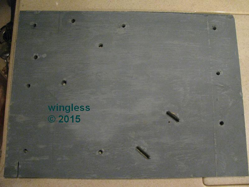
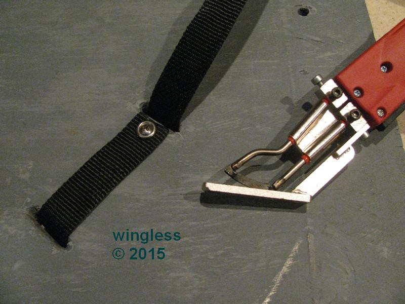
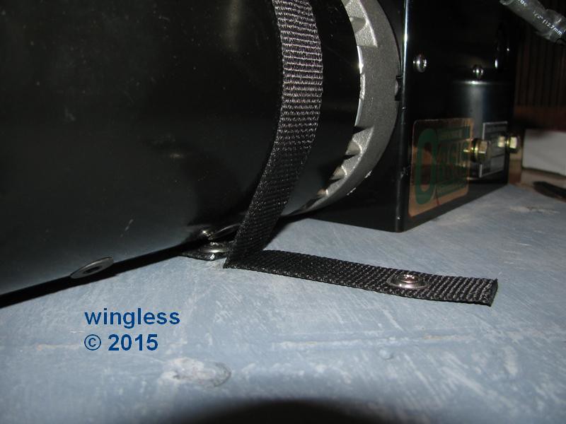
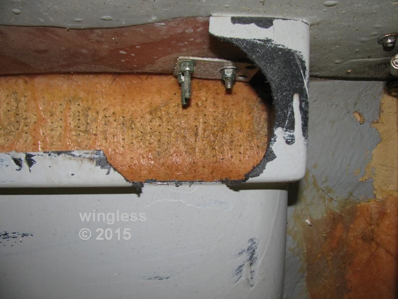
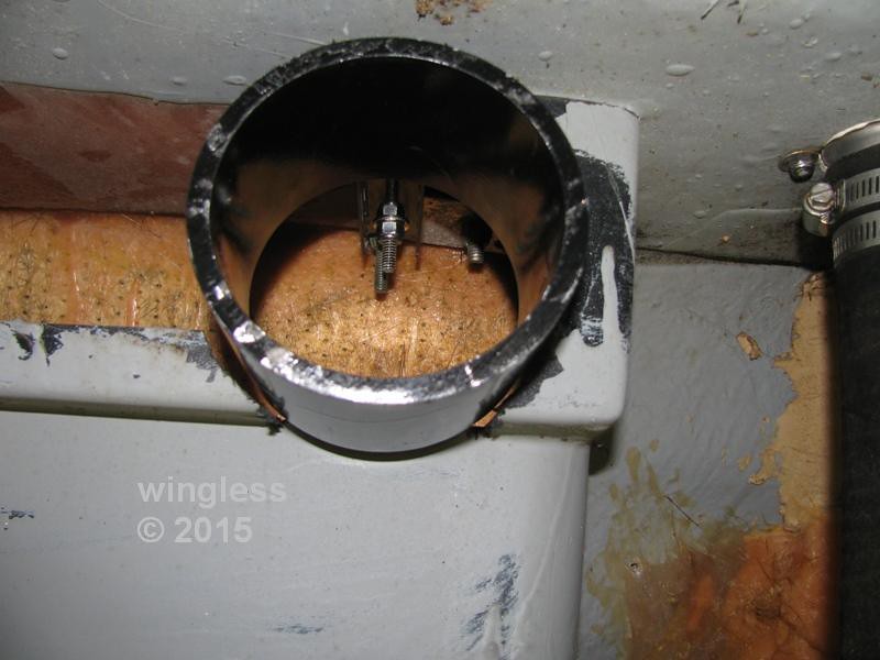
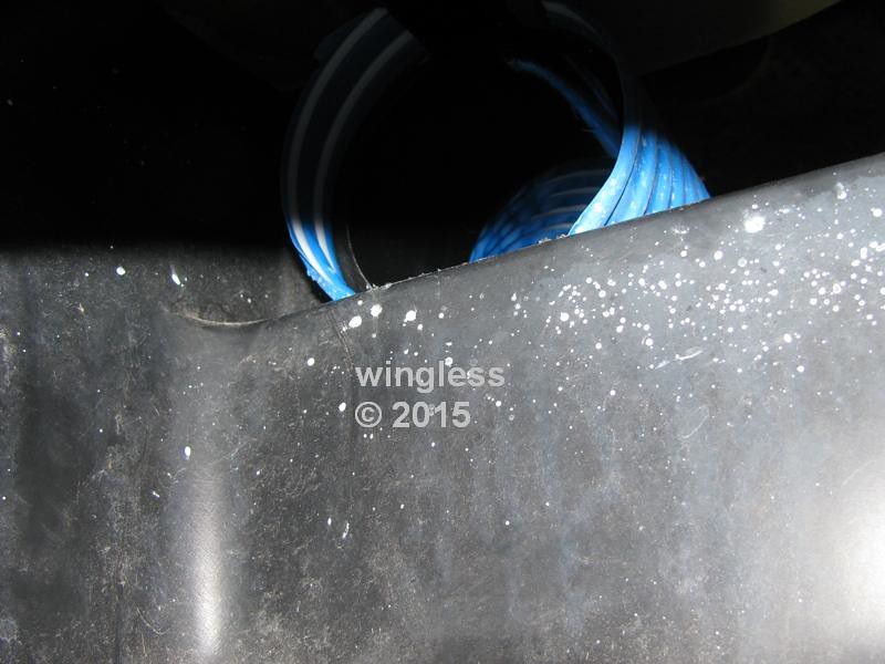
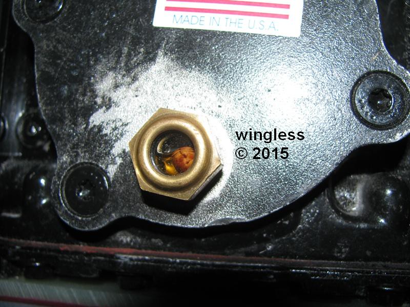
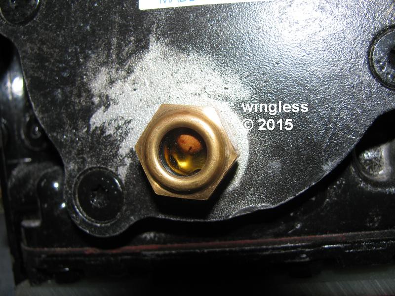
The compressor is located in an inaccessible / unusable area of the hull, between the inner and outer hull. This volume is outside the ignition-protected environment, where it is prohibited / unwise to install anything that makes a spark, like this compressor, that could ignite gasoline vapors, even though those vapors should not exist. This is an ABYC (boat) requirement. When I inspect the compressor, like for checking the oil level, I need to unscrew and slide-out the ice maker. Then I have excellent access.
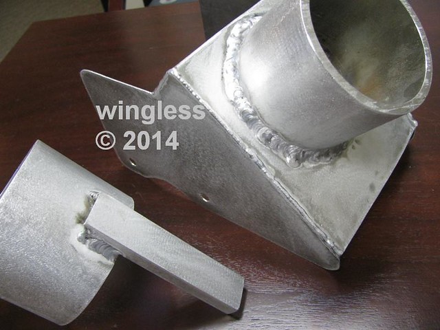
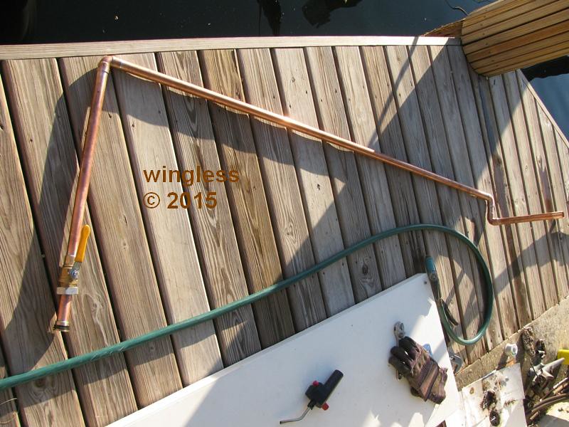
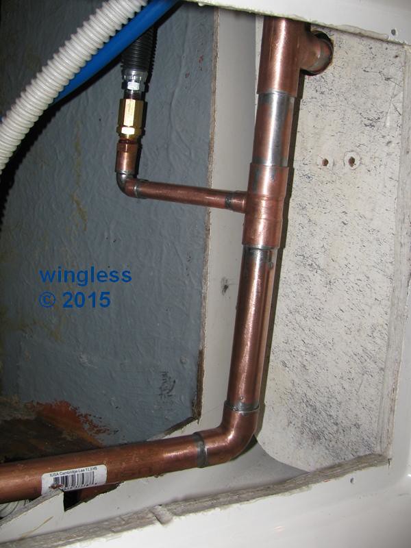
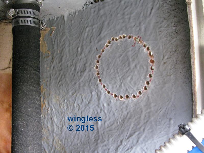
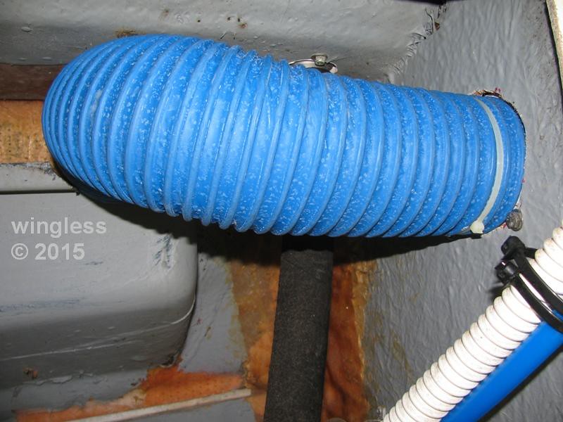
The compressor location has access to exterior air, but not enough to provide acceptable cooling. My system has one of these 4" 220CFM SHURflo yellowTAIL In-Line Blowers w/ ducting to the exterior, then to a custom shroud dumping onto the compressor cylinders / head.
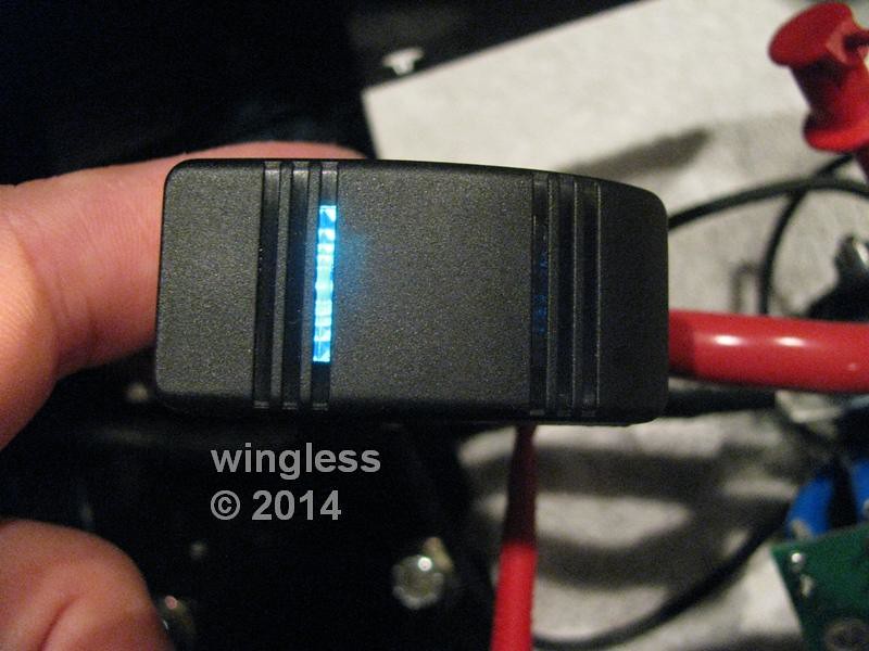
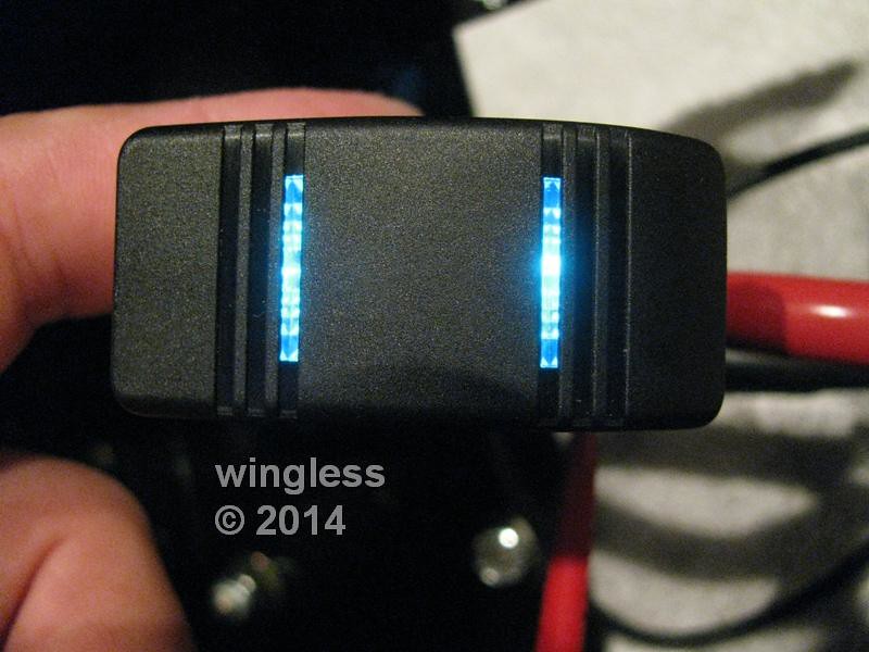
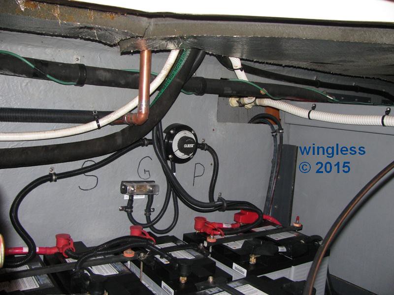
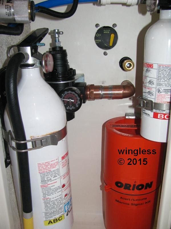
This location is very handy. It is directly above my battery bank. I am using one of these 200A Blue Seas Systems 187-Series Circuit Breakers to provide both the circuit protection and the power feed on / off function. The compressor is wired to power the fan whenever the compressor is running. I will monitor the head temperature to determine if it would be better to reconfigure the fan power to have the fan instead thermostatically controlled. I also have a dash-panel enable / disable switch for the compressor.