K5LA Help

Guys,

I got my K5LA kit from hornblasters Thursday and am starting to put it together tonight. The kit and horns look great, I’m really looking forward to getting it going.

Problem is, my kit came without any instructions. I found the manual and diagram on the web site and that is some help.

But frankly, this is my first “air” project, I’m a rookie. I’ve never modified a vehicle. I was wondering if a more detailed instruction kit exists?

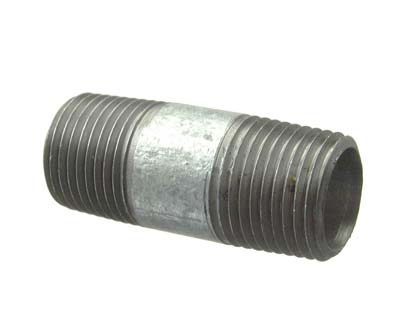
Or does anyone have a parts list that shows a diagram of what all these parts are?

I know, sorry for being a dope, but I don’t want to screw this up!

Thanks,

Paul

What are you installing it on?

Thanks.

A 2004 Silverado. I’m having a body shop fabricate something to mount the horns onto, and they’ll go where the spare was. But speaking of the horns, there appears to be 3 places where the airline could connect to… at the top of the round mounting bracket where a red plastic plug is screwed in by hand (which would be covered if that was used to attach to a bracket). There are 2 plugs on the sides of the manifold.

  1. I’m assuming I could remove one of the plugs from the side of the manifold, insert that into the top, and connect the air line into the side I removed the plug from?

BTW, I like those blue bonnets you have on your horns. Where did you get those from?

Thanks

I found this on hornblasters… Its not for your kit its for the shocker horns, however the wiring should be about the same. The last page is the most helpful http://www.hornblasters.com/diagrams/mnl-hb4h1520gcc.pdf… Someone on here probably has a better idea but worst comes to worst you can improve with this.

Twist,

Thanks, but I have there is one of those for the K5LA on the site. The diagram is pretty basic, as are the directions. But there are a lot of parts to this kit, I guess I’m just going to have to spend time figuring out how it all goes together.

Thanks

use this write up for an outline on how its done
http://www.trainhornforums.com/thread170.hb4h_install_tutorial.html

if you try to use one of the side ports which it will work, you will need a 1/2 inch plug, because the side plugs are 3/8 i wouldnt recommend going for side ports cause the 5a bell wouldnt sound correctly if done so

Use the 1/2" side port and plug the flange (round mount) port with a 1/2" plug you can buy at Lowes or use the plug you removed. Don’t use the 3/8 side port. I use the side port for my metering valve and the flange port for the solenoid. The blue bonnets I bought on ebay, they do a great job of keeping debris out of the chimes since they face forward.

Actually one port is 3/8" and the other is 1/2". Using the side ports do not alter the sound at all.

Thanks guys. I’ll be spending some time on this Sunday. I’m sure I’ll be posting a list of questions Sunday night :slight_smile:

I did see that, and it is a nice write up. Thanks.

We’re ready for any questions you may have. Do yourself a favor and avoid any frustration when dealing with air leaks…Use blue Loctite on all your brass fittings holding constant pressure. When using Loctite there is no need to over tighten the fittings. Just give it a few minutes to dry before pressuring up your system.

Alright, guys, I have a few bones to pick here. I consider myself to be a reasonable person and I’m usually the LAST person to complain. Frankly, I wouldn’t normally do this here, however my email sent one week ago today to “support@hornblasters.com” requesting whatever is available in the way of diagrams, instructions or explanations for the K5LA kit has for whatever reason gone unanswered.

  1. I wrote the email because my kit came with no directions, diagrams, nada.

  2. No one is perfect, and I can appreciate that maybe 1 or 2 kits out of 100 shipped might be missing something. So after some searching around on the website I was able to find and download a 6 page “K5 Train Horn Kit Installation Guide”, [NAK55G40.pdf] from:

http://www.hornblasters.com/support/manuals_and_schematics

which includes one very basic schematic of the major system components.

  1. What it doesn’t contain, which frankly is frustrating the snot out of me, is:

    (a.) A parts list/inventory including a diagram/description of all the parts.

    (b.) 4. A DIAGRAM that shows the specific parts assembly for each major system assemblies. (i.e.) Air Compressor to Tank, Pressure Switch In to Tank, and so on.

Understand that I’m mechanically inclined, and if I have even reasonable instructions/diagrams for installing or repairing most anything, I can do it. It seems as if many of you have other air applications on your vehicles, so you can probably assemble these kits with or without directions. But if a K5LA train horn kit is someone’s first air project install, good luck trying to do it with these instructions.

Example from page 3:

Air Horns to Tank:

[Air Tank] >> [1/2 to 1/2 NPT Nipple] >>[Air Valve] >> [1/2" Push-To-Connect Fitting] >> [1/2" Air Line] >> [1/2" Push-To_Connect Fitting] >> [K5 Manifold]

If an exploded diagram of this assembly was included, I’m sure this would make sense. Without it, this is gibberish.

  1. The directions I downloaded provides a link: www.hornblasters.com/support Click on that link and you’ll get: 404 Error: Requested Resource Not Found

I have spent several hours combing through this forum during the past week looking for resources, either diagrams or photos of other K5LA installs. And I have spent time googling the description of several of the parts in this kit to try and understand what they are. While several photos from member’s installs can be found, they tend to show the vehicle, the horns, and maybe the tank from a larger perspective. Many of you have larger tanks and equipment that are well beyond what comes in the kit.

Lastly, for the $ I invested in this hornblasters kit, and given that hornblasters has now been in business for years, there is no reason why better assembly instructions with diagrams, at least for THIS specific kit are not available. I shouldn’t have to call someone in tech support to have it explained to me. That’s a waste of everyone’s time. And I don’t think it should be left to the forum members who have bought and installed these kits to post pictures of their install because hornblasters hasn’t developed adequate directions & diagrams.

I’m sorry to biatch :mad: guys, I really am, because my impression of both hornblasters and you guys here on this forum is that you’re a good and fun group of guys. And I’ve enjoyed being here for the 2 weeks or so that I have been registered.

I’m just frustrated with the lack of documentation, and I shouldn’t be.

PC1

give them a buzz let them know your not satisfied im sure they wont mind…

Saturday A.M. update…

Called tech support. Aaron from sales is available, if I wanted to purchase something. Tech support is normal business hours M-F.

It looks like I’m going to have to invest some more time trying to figure this out. Shouldn’t be this way.

hold on i’m writing you up something brb

this example is telling in what order to connect the parts…

on one of the ports od your tank install a 1/2" nipple.

then connect your air valve to the nipple that you just installed.

you should either have a 1/2 in compression fitting or push to connect fitting.

or

then install your airline to the fitting you used if its a push to connect you simply push the hose into the fitting as far as it will go, if its a compression fitting it will have a nut and a ferrel that you will tighten down to secure the airline.

Run your airline from there to your horns and install another fitting on your horns and connect the airline there.

allthought these instructions are a little backwards to me because if it were me i would reversr these and install the valve closest to the horns and not the tank.

hope this helps you

if you need wiring help let me know

V7 & Twist.

Yeah, this is helpful. I’ll give this a go later this afternoon-evening. Thank you for your help.

PC1